Help Center
Deliver to:
Ship to
Currency
USD (US Dollar)

Save
Your Cart
Your quote requests is empty.
Welcome back! If you had Quote requests items in your Shopping cart, we have saved them for you. You can Sign in now to see them, or whenever you're ready to check out.
Total $0.00
View Cart
Free DFM Feedback With Your Quote
No Minimum Order Quantities
Lead times as fast as 5 day
Get instant quote
Instant Quote
Upload 3D files for an instant quote. More than 10 kinds of materials are listed online, and from one piece prototype to mass production.
Quality Assurance
A strictly vetted and managed network.
Online Order Tracking & Management
Track production status, reorder parts and manage your order history all in one place.
Sheet Metal Fabrication Service
Available materials for sheet metal
PMMA (Acrylic)
Mill Lead Time:
Finishing Options:
Type:
PMMA (Acrylic)
Learn more
Carbon Fiber
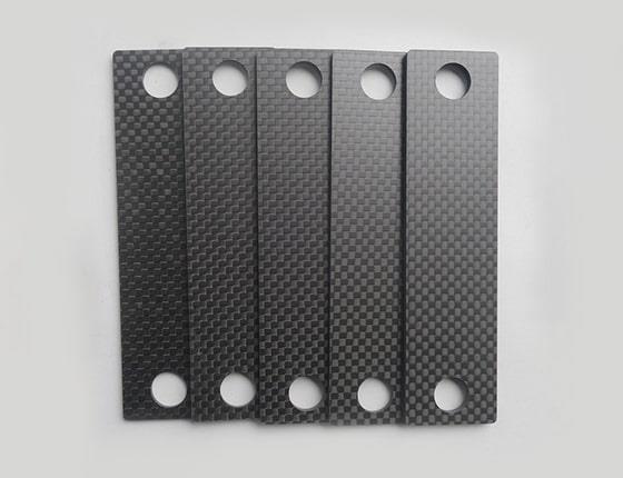
Carbon fiber (CF) is a new type of fiber material with high strength and high modulus fiber containing more than 95% carbon.
Mill Lead Time:
Finishing Options:
Type:
Carbon Fiber Plate
Learn more
Carbon fiber (CF) is a new type of fiber material with high strength and high modulus fiber containing more than 95% carbon.
Aluminum
Mill Lead Time:
Finishing Options:
Type:
Aluminum 5052,Aluminum 6061
Learn more
Stainless steel
Mill Lead Time:
Finishing Options:
Type:
Stainless steel 304,Stainless Steel 316/316L,Stainless steel 201,Stainless Steel 301
Learn more
Mild steel
Mill Lead Time:
Finishing Options:
Type:
Mild steel 1018
Learn more
Copper
Mill Lead Time:
Finishing Options:
Type:
Copper C110,Copper 260 (Brass),Copper 101
Learn more
Physical and mechanical properties are not guaranteed. They are intended only as a basis for comparison and not for design purposes.
Available surface finishes for sheet metal
Image Name (10) Applicable Materials Colors Description
Standard (As-Milled) (Ra 125μin) Standard (As-Milled) (Ra 125μin) Metals, Plastics
The finish option with the quickest turnaround. Visible tool marks, potentially sharp edges and burrs would be removed by default.
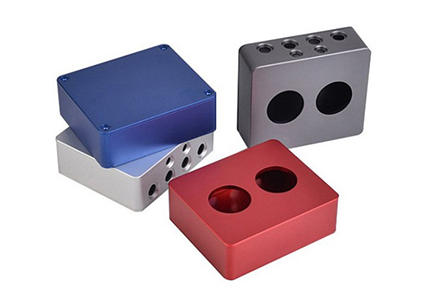
Bead blast + Anodized color Bead blast + Anodized color Metals
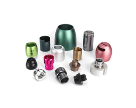
Anodizing creates a corrosion-resistant finish. Parts can be anodized in different colors—clear, black, red, and gold are most common—and is usually associated with aluminum.
Anodized Anodized Metals, Plastics
It creates a corrosion-resistant finish. Parts can be anodized in different colors—clear, black, red, and gold are most common—and is usually associated with aluminum.
Electrically conductive oxidation Electrically conductive oxidation Metals
It creates a corrosion-resistant finish, the film produced by conductive oxidation is only 0.01-0.15 micrometers,
Black oxide Black oxide Stainless steel, steel
Black oxide is a conversion coating used to improve corrosion resistance and minimize light reflection.
Brushed Brushed Metals
Brushing is a surface treatment process in which abrasive belts are used to draw traces on the surface of a material, usually for aesthetic purposes.
Bead Blast Bead Blast Metals, Plastics
The part surface is left with a smooth, matte appearance.
Spray painting - Matt paint Spray painting - Matt paint Aluminum, Titanium, Plastics
Applicable to all pantone colors-Matt
Spray painting: Using spray guns with air pressure to disperse into uniform and fine droplets and apply the painting to the surface of the object.
Spray painting - High gloss paint Spray painting - High gloss paint Metals, Plastics
Applicable to all pantone colors-High gloss
Spray painting: Using spray guns with air pressure to disperse into uniform and fine droplets and apply the painting to the surface of the object.
Powder coat - Matt Powder coat - Matt Metals
Applicable to all pantone colors-Matt
This is a process where powdered paint is sprayed onto a part that is then baked in an oven.
Available sheet metal fabrication processes
Our network of Manufacturing Partners gives you easy access to sheet metal fabrication capabilities to serve all your manufacturing needs.
Name Description Allowable sheet thickness
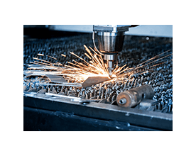
Laser cutting This manufacturing process uses a high-power laser beam to cut a material sheet. This manufacturing process uses a high-power laser beam to cut a material sheet.
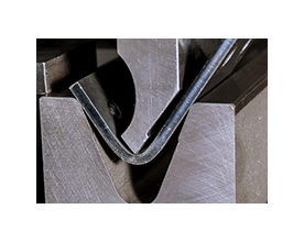
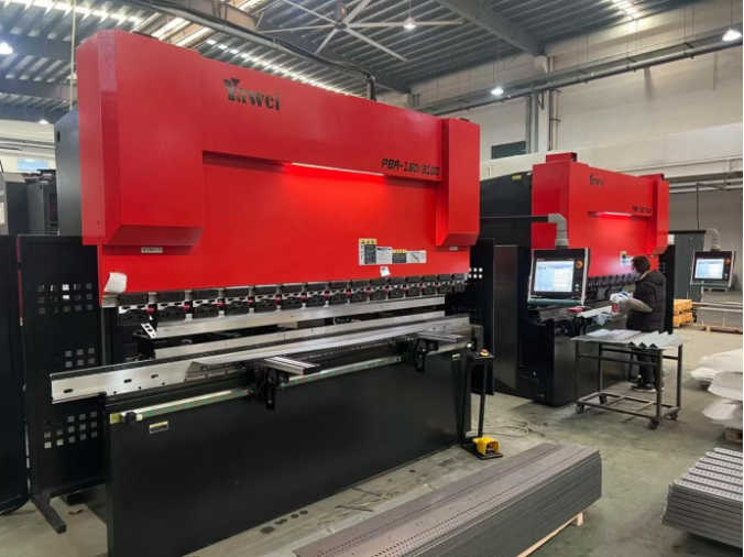
Bending This manufacturing process uses dies to produce a U-shape, V- shape or channel shape along a straight axis in ductile materials. 1-6mm (depending on material)
Tolerances for sheet metal fabrication
Feature Tolerance
Cutting feature ± .00787’’ (0.2 mm)
Bend angle ± 1.0°
Bend to edge +/- 0.010” (0.254mm)
TECHNOLOGY OVERVIEW
What Is Sheet Metal Fabrication?
The Basics Of Sheet Metal Service
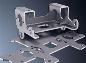
Sheet metal processing is a comprehensive cold processing process for thin metal plates (usually below 6mm), including shearing, punching, bending, welding, riveting, mold forming and surface treatment. Its notable feature is that the thickness of the same part is the same.
How Sheet Metal Works
1.Sheet metal processing method
Non-mold processing: the processing of sheet metal through digital punching, laser cutting, shearing machine, bending machine, riveting machine and other equipment is generally used for sample production or small batch production, and the cost is relatively high. The processing cycle is short and the response is quick.
Mold processing: Through fixed molds, sheet metal is processed, generally there are blanking molds and forming molds, which are mainly used for mass production, and the cost is low. The mold cost is high in the early stage, and the quality of the parts is guaranteed. The early processing period is long and the mold cost is high.

2.Sheet metal processing
Cutting: digital punching, laser cutting, shearing machine
Forming - bending, stretching, punching: bending machine, punching machine, etc.
Other processing: pressure riveting, tapping, etc.
Welding: the way sheet metal is joined
Surface treatment: powder coating, electroplating, brushing, laser engraving, silk screen, etc.
FAQ's
What is sheet metal?

Sheet metal refers to a thin, flat piece of metal that can be formed and manipulated into various shapes and sizes. Sheet metal can be made from a variety of metals, including steel, aluminum, copper, brass, and nickel.

Sheet metal can be produced in a range of thicknesses, typically ranging from 0.006 inches to 0.25 inches, depending on the material and application. It can be produced in coils or sheets and can be cut, stamped, bent, or welded to create a variety of parts and products.

Sheet metal is commonly used in the manufacturing of a wide range of products, including:

1. Automotive parts: Sheet metal is used to make a variety of automotive parts, including body panels, bumpers, doors, and roofs.

2. Aerospace parts: Sheet metal is used to make components for aerospace structures, including wings, fuselages, and landing gear.

3. HVAC systems: Sheet metal is used in the fabrication of ductwork, air conditioning units, and furnace components.

4. Building construction: Sheet metal is used in the construction of roofs, gutters, and façades.

Sheet metal fabrication involves working with the metal to cut, form, and assemble it into the desired shape. Common sheet metal fabrication processes include cutting, punching, bending, and welding. These processes can be performed manually or using automated equipment, depending on the complexity of the part and the required production volume.


What types of materials are commonly used in sheet metal fabrication?

Sheet metal can be made from a range of different metals and alloys, each with their own unique properties, advantages, and disadvantages. Here are some of the most commonly used materials in sheet metal fabrication:

1. Steel: Steel is the most commonly used metal in sheet metal fabrication. It is a strong, durable, and cost-effective material that can be easily formed and welded. Steel is used to make a wide range of products, including automotive parts, appliances, and building materials.

2. Aluminum: Aluminum is a lightweight and corrosion-resistant metal, making it ideal for use in the aerospace, automotive, and construction industries. Aluminum is also readily available and easy to work with, making it a popular choice for sheet metal fabrication.

3. Copper: Copper is a highly conductive and corrosion-resistant metal that is often used in electrical and plumbing applications. It is also commonly used to make decorative objects and home furnishings.

4. Brass: Brass is a copper-based alloy that is often used in decorative applications due to its attractive golden color. It is also commonly used in the manufacture of musical instruments and plumbing fixtures.

5. Nickel: Nickel is a strong and corrosion-resistant metal that is often used in high-temperature applications, such as aerospace and industrial manufacturing. It is also used in the manufacture of coins and jewelry.

6. Titanium: Titanium is a lightweight, strong, and corrosion-resistant metal that is commonly used in the aerospace, military, and biomedical industries.

The choice of material used in sheet metal fabrication depends on the specific application, required properties of the finished product, and the cost.


What is the difference between sheet metal and plate metal?

Sheet metal typically refers to metal that is less than 6mm in thickness, while plate metal refers to metal that is 6mm or thicker.

What is the difference between sheet metal bending and sheet metal folding?

Sheet metal bending and sheet metal folding are both methods of shaping sheet metal into various forms, but they differ in the way that the metal is manipulated.

Sheet Metal Bending: Sheet metal bending is a process of forming sheet metal into a desired shape by bending the metal around a straight axis, using a press brake machine. A press brake is a machine that consists of upper and lower dies, which clamp the sheet metal securely and apply pressure to bend the material to the desired angle.

The bending process generally produces a V-shape, U-shape, or channel-shape in the sheet metal. The bend radius and angle can be controlled precisely using specialized tooling and bending dies.

Sheet Metal Folding: Sheet metal folding, also known as edge bending, is a process of forming sheet metal using a folding machine. The folding machine bends the metal along a straight axis or a curved line, producing a crisp and clean fold. The fold is typically created using a punch and a die, which grip and bend the metal along a straight or curved line, creating a fold range that can be limited to 180°.

Sheet metal folding is ideal for producing shapes with folded edges such as panels with flanges or boxes.

The choice between sheet metal bending and sheet metal folding will depend on the specific requirements of the part, including the desired shape, bend angle, and production volume. For larger volumes or parts requiring more precise and complex bends, sheet metal bending is often the preferred choice, while sheet metal folding is ideal for parts with straight edges and simple bends.

What is the minimum bend radius for sheet metal?

The minimum bend radius for sheet metal depends on several factors, including the material thickness, the type of material, and the tooling used to make the bend. As a general rule, the minimum bend radius for sheet metal should be at least equal to the material thickness.

For example, if the sheet metal is 1 mm thick, then the minimum bend radius should be 1 mm. However, certain materials may require a larger bend radius due to their physical properties. Materials that are more brittle or have a greater yield strength may require a larger bend radius to prevent cracking or deformation.

The tooling used to make the bend also plays a critical role in determining the minimum bend radius. The punch and die used to make the bend should be designed with a radius that matches the minimum bend radius of the material, ensuring that the bend is consistent and does not cause damage to the metal.

It's important to note that the minimum bend radius is not the same as the maximum bend angle. The maximum bend angle for sheet metal is generally around 180 degrees, although this can vary depending on the thickness and type of material being used. The minimum bend radius is a key consideration in sheet metal bending to ensure that the bend is precise, consistent and does not result in defects in the finished part.

Sheet Metal Design Practical Tips


Hello everyone, I’m Xiang, a sheet metal structural designer with over a decade of industry experience. I work closely with production shops daily on bending, welding, and laser cutting processes, and I’ve encountered countless manufacturing pitfalls over the years. Many designs look perfect on drawings yet prove unfeasible to bend on the shop floor, suffering from bending cracks and misaligned hole positions—issues I faced constantly early in my career.

Today I’ll skip overly theoretical jargon and share down-to-earth, actionable practical tips you can implement immediately to reduce manufacturing errors.

1. Material Selection: Match Specs to Requirements; Avoid Over-Thickening Sheets
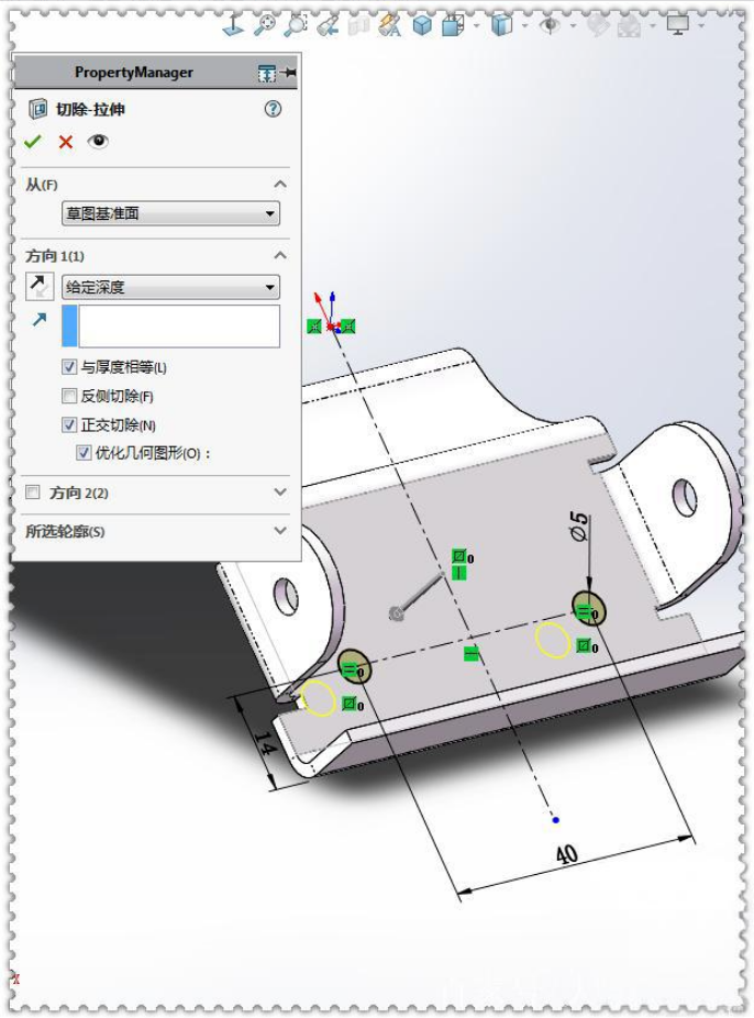
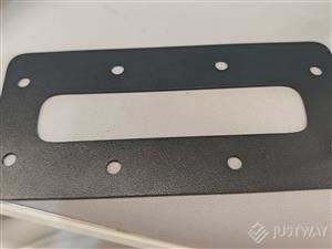
Many junior designers arbitrarily specify thicker sheet metal out of concerns for structural rigidity, which drastically raises production costs while increasing bending difficulty. Below are standard material thickness guidelines for common applications ready for direct reference:

  • Standard cabinets, enclosures & general chassis: 1.2 mm / 1.5 mm cold rolled steel (CRS); compatible with standard tooling, zero bending complications
  • Load-bearing brackets & base structural components: 2.0 mm – 2.5 mm, sufficient for load stability
  • Lightweight cosmetic parts: 1.0–1.2 mm aluminum alloy; easy to machine with superior corrosion resistance
  • Humid outdoor environments: Stainless steel is mandatory. Cold rolled steel with paint coating is not a viable substitute, as rust rework will be inevitable down the line.

Quick Reminder: Standardize sheet thickness within a single product series to minimize tool changes and machine setup downtime for production.

2. Bending Design – The Most Error-Prone Process Stage

2.1 Standardize Internal Bend Radii; Prioritize R = Sheet Thickness

Example: For 1.5 mm sheet metal, set internal bend radius to 1.5 mm. Avoid varying radii on a single part, as frequent die swaps lead to dimensional inconsistencies. Increase radii for stainless steel parts to prevent surface cracking during bending.

2.2 Offset Holes Away From Bend Lines to Eliminate Hole Distortion

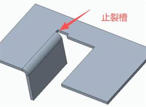
This is a common mistake among new designers: holes positioned too close to bend lines will stretch and deform during bending, rendering parts scrap. If structural constraints prevent repositioning holes, add stress relief notches or score grooves in advance to release internal stress and stop tearing & distortion.

2.3 Stress Relief Notches Are Mandatory for Closed Corner Joints

Closed right-angle corners without notches will consistently bulge and crack at edges during forming. Simplified design rule: Notch width ≥ sheet thickness for straightforward shop fabrication without complex calculations.

3. Stiffening Principle: Bend Formed Reinforcements Over Welded Stiffeners

When flat panels suffer deflection and flexibility, welding angle iron stiffeners is an inefficient default solution.

Core Rule: Prioritize bent integral reinforcements over welded reinforcements wherever possible.

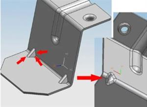
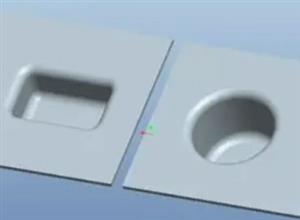
  • Large flat panels: Form embossed stiffening ribs – zero extra cost, no welding distortion, drastically improved rigidity
  • Tall reinforced structures: Hemming & folded edge forming for one-piece construction, precise dimensions and smooth cosmetic surfaces
  • Assembled joint structures: Split components into single bent pieces where feasible to reduce assembly welding. Welding inevitably introduces distortion, requiring labor-intensive flattening and finishing that drives up coating costs.

4. Assembly Design: Reserve Tolerance Allowances for Shop Production

  • Mating fastener holes: Oversize holes by 0.2–0.3 mm unilaterally to compensate for cutting and bending tolerances, eliminating on-site hole reaming
  • Snap-fit structures: Snap thickness ≥ 1x sheet thickness; add stress relief notches at bend sections to prevent fracture during repeated assembly & disassembly
  • Contact mating surfaces: Avoid full-surface contact; incorporate clearance cutouts to accommodate minor sheet deformation and simplify assembly fit-up.

5. Clinch Fasteners & Welding Guidelines

  • Clinch nuts & studs: Maintain edge clearance greater than the outer diameter of clinch hardware to prevent bulging and cracking at sheet edges
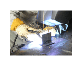
  • Thin sheet welding: Skip full continuous welds, which induce severe distortion; intermittent spot welds deliver adequate structural strength
  • Cosmetic weld seams: Reserve sufficient grinding access space; eliminate blind weld corners to streamline surface finishing processes.

6. Three Critical Drafting Habits for New Sheet Metal Designers

  • Coordinate with production shops prior to modeling: Confirm existing bending die dimensions to align designs with available tooling and avoid custom die expenses
  • Produce prototype drawings for complex bent parts, review with bending technicians before finalizing 3D models
  • Include all critical annotations on production drawings: sheet thickness, material grade, burr orientation, bend radii, hole dimensions to cut down communication delays and errors.

Closing Notes

The core tenet of sheet metal structural design can be summed up simply: optimize for manufacturability, ease of assembly, minimal material waste, and controlled production costs.

Sheet Metal Fabrication Case Study
Sheet metal fabrication resources for engineers