Help Center
Deliver to:
Ship to
Currency
USD (US Dollar)

Save
Your Cart
Your quote requests is empty.
Welcome back! If you had Quote requests items in your Shopping cart, we have saved them for you. You can Sign in now to see them, or whenever you're ready to check out.
Total $0.00
View Cart
Free DFM Feedback With Your Quote
No Minimum Order Quantities
Lead times as fast as 2 weeks
Get instant quote
Instant Quote
Upload 3D files for an instant quote. More than 10 kinds of materials are listed online, and from one piece prototype to mass production.
Quality assurance
A strictly vetted and managed network.
Online Order Tracking & Management
Track production status, reorder parts and manage your order history all in one place.
Injection Molding Processes
Injection Molding Materials
ABS
Mill Lead Time:
Finishing Options:
Type:
ABS
Learn more
POM
Mill Lead Time:
Finishing Options:
Type:
POM
Learn more
Nylon
Mill Lead Time:
Finishing Options:
Type:
Nylon
Learn more
Polycarbonate (PC)
Mill Lead Time:
Finishing Options:
Type:
Polycarbonate (PC)
Learn more
PC/ABS
Mill Lead Time:
Finishing Options:
Type:
PC/ABS
Learn more
PVC
Mill Lead Time:
Finishing Options:
Type:
PVC
Learn more
Polyethylene (PE)
Mill Lead Time:
Finishing Options:
Type:
Polyethylene (PE)
Learn more
Polypropylene (PP)
Mill Lead Time:
Finishing Options:
Type:
Polypropylene (PP)
Learn more
Polystyrene (PS)
Mill Lead Time:
Finishing Options:
Type:
Polystyrene (PS)
Learn more
TPU
Mill Lead Time:
Finishing Options:
Type:
TPU
Learn more
Physical and mechanical properties are not guaranteed. They are intended only as a basis for comparison and not for design purposes.
Injection Molding Finishes
Glossy Semi-Glossy Matte Textured
SPI-A2 ±0.1mm ±0.05mm MT (Moldtech)
SPI-B1 SPI-B2 ±0.1mm VDI (Verein Deutscher Ingenieure)
SPI-B3 ±0.2mm YS (Yick Sang)
Secondary Operations
Spray Paint
A spray gun or disc atomizer, with the help of pressure or centrifugal force, disperses into uniform and fine mist droplets, which are applied to the surface of the object to be coated.
Laser Engraving
Laser technology is used to engrave text on objects. The characters engraved by this technology have no notches, the surface of the object is still smooth, and the writing will not wear out.
Silk Screen
Use photosensitive materials to make screen printing plates by photoengraving (make the screen holes of the graphic part on the screen printing plate be through holes, and the screen holes of the non-graphic part are blocked). During printing, through the extrusion of the scraper, the ink is transferred to the substrate through the mesh of the graphic part, forming the same graphic as the original.
Ultrasonic Welding
The high-frequency vibration waves are transmitted to the surfaces of two objects to be welded, and under pressure, the surfaces of the two objects are rubbed against each other to form fusion between molecular layers.
TECHNOLOGY OVERVIEW
How Injection molding works?
The Basics Of Injection Molding Service
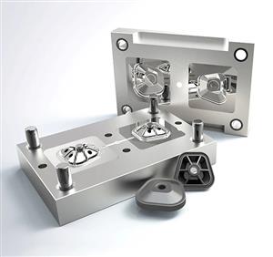
Injection molding is a manufacturing process for mass producing parts. It is most commonly used to mass-produce the same parts on a large scale, and the general formal production scale is tens of thousands or even millions of times. The molten plastic is injected into the mold of the plastic product by pressure, and cooled and formed to obtain various plastic parts. There are mechanical injection molding machines specially designed for injection molding. The most commonly used plastics are polyethylene, polypropylene, ABS, PA, polystyrene, etc.
How Injection Molding Works
1. Put the mold into the injection molding machine (IMM), the injection molding machine closes the mold, under the action of the clamp, the mold is kept closed during the plastic injection molding.
2. Feed the plastic in the shape of granules or pellets into the injection molding machine.
3. The injection molding machine heats the plastic until it becomes liquid.
4. The injection molding machine nozzle then injects the molten plastic into the mold (injection pressure). At this moment, the mold cavity is filled with plastic liquid. These liquids form solid products upon cooling.
5. Finally, the ejector (linked to the ejector system) discharges the cooled product from the machine as a finished part.
FAQ's
What is injection molding?

Injection molding is a manufacturing process used to create plastic parts in large quantities. Molten plastic material is injected into a mold or cavity, which is then cooled and solidifies into the desired shape. The process involves feeding plastic pellets into a hopper, which are then heated to a molten state and injected into the mold under high pressure. This pressure ensures that the material fills the mold completely and uniformly, resulting in a high-quality finished product. Injection molding is commonly used to create products such as toys, automobile parts, packaging materials, and medical devices.

What materials can be used in injection molding?

A variety of materials can be used in injection molding, including thermoplastics, thermosets, and elastomers.

Thermoplastics: These are the most commonly used materials in injection molding, including polyethylene (PE), polypropylene (PP), polystyrene (PS), acrylonitrile-butadiene-styrene (ABS), and polyvinyl chloride (PVC).

1. Thermosets: These materials are harder, more rigid, and more heat-resistant than thermoplastics. Examples include epoxy resins and phenolic resins.

2. Elastomers: These are rubber-like materials with high elasticity and flexibility. Examples include silicone, natural rubber, and styrene-butadiene rubber (SBR).

The choice of material depends on the specific application and requirements for the finished product. Properties such as strength, durability, flexibility, heat resistance, chemical resistance, and color can be tailored by using different materials and additives in the plastic pellets. In addition, recyclable and biodegradable materials are becoming increasingly popular in injection molding as part of a sustainable production process.

What are the different types of injection molding machines?

Single-shot injection molding and multi-shot injection molding are both methods used for producing plastic parts, but they differ in the way that the plastic material is injected into the mold.

Single-shot injection molding: This is the most common method of injection molding. It involves injecting a single material into the mold, which solidifies to form the final part. The mold is typically designed to have a single cavity or multiple cavities, enabling multiple identical parts to be produced simultaneously.

Multi-shot injection molding: This method uses multiple materials to create a single part. It is also known as overmolding. Depending on the design of the mold, two or more materials can be injected into the mold in a single operation. Multi-shot injection molding allows for the creation of parts with multiple colors or materials, or for the creation of parts with rigid and flexible sections.

There are two main types of multi-shot injection molding:

1. Sequential injection molding: This involves injecting one material into the mold cavity and allowing it to partially solidify before injecting the second material. The process can be repeated with additional mold cavities to create more complex parts.

2. Co-injection molding: This involves injecting two materials simultaneously into the mold cavity. This method is typically used for creating parts with a core and skin structure, for example, plastic cups with foam insulation.

The choice of single-shot or multi-shot injection molding largely depends on the specific requirements of the part and the manufacturing process. Multi-shot injection molding is more complex and can be more expensive, but it allows for greater design flexibility and the creation of parts with multiple materials or colors.


What is the maximum injection molding capacity of a machine?

The maximum injection molding capacity of a machine depends on several factors, including the volume of the mold cavity, the shot size, and the material being used. The machine's clamping force and injection pressure also play a role in determining the maximum injection molding capacity.

Injection molding machines can range in size from small benchtop machines with a maximum injection capacity of a few grams to large machines capable of producing parts that weigh several kilograms. High-capacity, industrial-grade machines can have a maximum injection capacity of up to 60,000 grams (or 60 kilograms), depending on the manufacturer and model.

The maximum injection molding capacity of a machine is typically specified in terms of the shot size, which is the maximum volume of material that the machine can inject into the mold with a single injection stroke. The shot size can range from a few grams to several kilograms, depending on the machine's size and capacity.

It's important to note that while a machine may have a high maximum injection molding capacity, the actual production rate will depend on the complexity of the part being produced, the cycle time, and the number of cavities in the mold.

Plastic Part Cosmetic Defect – Black Specks | Definition, Causes & Inspection Criteria

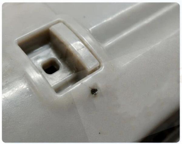
1. Definition

Black specks refer to black spots or streaks present on molded parts. Any black discoloration visible on the component surface is defined as BS (Black Specks).

2. Visual Characteristics

Typically appear as black dot-like or linear foreign inclusions

Mostly found on the part surface

Negatively impacts cosmetic uniformity

3. Potential Causes

Degraded / Burnt resin

Carbonized resin

Material stagnation residue inside barrel

Contamination from foreign debris

----------------------------------------------------------------------------------------------------------------------------------------------------------------

Inspection Criteria

Observe color and distribution pattern

Verify whether the defect is a foreign contaminant

Distinguish between surface residue and embedded inclusions

Retain photos and defective samples

Plastic Part Cosmetic Defect – Pitting (Pockmarks) | Definition, Causes & Inspection Criteria

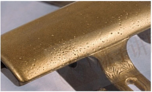
1. Definition

Pockmarks are small depressions formed on thick-section molded areas, caused when molten resin fails to fully adhere to the mold cavity surface.

2. Visual Characteristics

Tiny indentations on the part surface, generally small in size

Commonly found on thick wall sections

3. Main Causes

Pockmarks can stem from multiple factors; the primary contributor is insufficient pack pressure.

----------------------------------------------------------------------------------------------------------------------------------------------------------------

Inspection Criteria

Observe the location and density of indentations

Focus inspection on thick wall regions

Distinguish pockmarks from contamination or impact marks

Document size, affected zones and quantity


Plastic Part Cosmetic Defect Training – Simple Reference for Quality Inspectors

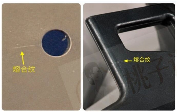
Plastic Part Cosmetic Defect – Weld Lines (Knit Lines) | Definition, Causes & Inspection Criteria

1. Definition

Weld lines form where separate resin flow fronts converge. They inevitably develop around perforations and appear as distinct linear marks on the surface.

2. Typical Locations

Surrounding holes, resin convergence zones, handles and folded angular geometries.

3. Favorable Conditions for Defect

More likely to occur at low mold temperatures, and become more pronounced when resin flow front merging is poor.

------------------------------------------------------------------------------------------------------------------------------------------------------

Inspection Criteria

Confirm position of linear marks

Evaluate impact on aesthetics and mechanical strength

Analyze in conjunction with hole locations, corners and melt flow direction

Take photos for archiving


Plastic Part Cosmetic Defect Training – Simple Reference for Quality Inspectors

Plastic Part Cosmetic Defect – Gas Burn | Definition, Causes & Inspection Criteria


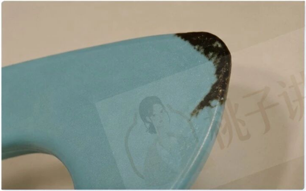
1. Definition

Gas burn describes scorched discoloration that appears on molded part surfaces during injection.

2. Formation Mechanism

Burn marks occur at melt flow end positions, most often associated with inadequate mold venting.

3. Typical Risks

Impairs surface appearance, local mechanical performance and perceived quality by customers. Severe cases are accompanied by carbonized traces.

Inspection Focus Points

Prioritize checking flow ends, corners and wall thickness transition zones

Confirm discoloration depth and affected area

Retain defective samples

Timely escalate venting concerns for mold optimization

Plastic Part Cosmetic Defect Training – Simple Reference for Quality Inspectors

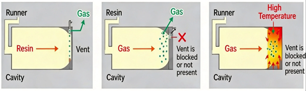
Plastic Part Cosmetic Defect – Root Cause of Gas Burn | Definition, Causes & Inspection Criteria

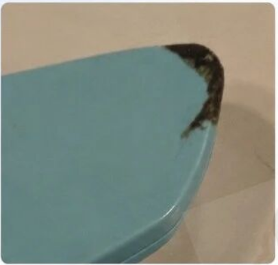
Local black or dark brown scorch marks appear on molded components.

Defect Formation Mechanism (3-stage process)

1. Normal Venting As resin fills the mold cavity, trapped air and gases generated by the molten material escape through mold vents.

2. Venting Blockage If vents become clogged, or no vents are present at melt flow ends, gases cannot be discharged smoothly.

3. Compression Heating & Burning Trapped gases are compressed, creating extreme localized high temperature, which scorches the resin.

Improvement Actions

Clean Vents

Regularly clean mold vent grooves and vent ports to ensure unobstructed ventilation.

Verify Venting at Flow Terminations

Install vents at melt flow end positions, avoid blind end sections without venting.

Optimize Fill Speed & Packing Pressure

Set appropriate filling speed and packing pressure to reduce gas entrapment and compression.

Inspect Mold Design & Maintenance Status

Periodically check mold structure, wear and clogging issues to maintain reliable venting performance.


Plastic Part Cosmetic Defect Training – Simple Reference for Quality Inspectors

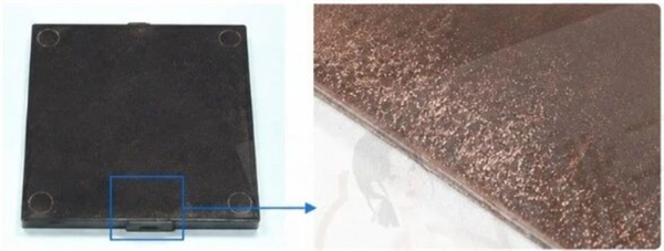
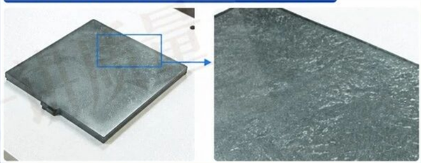
Plastic Part Cosmetic Defect – Glass Fiber Bloom | Definition, Causes & Inspection Criteria

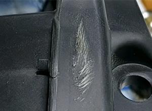
Glass Fiber Bloom (Glass Fiber Exposure)

The root causes for glass fiber bloom are identical to those for poor surface gloss.

Refer to the “Poor Surface Gloss” section for full details.

Figure 1: Glass fiber bloom on 120 square flat panel (Example 1)

Figure 2: Glass fiber bloom on 120 square flat panel (Example 2)

Definition / Appearance

Glass fibers emerge onto the molded part surface; localized whitening, fuzziness, rough texture or distinct fibrous grain patterns can be observed.

Relationship with Poor Surface Gloss

Glass fiber bloom shares the same root causes as poor surface gloss. Fundamentally, both defects originate from inadequate surface replication and abnormal surface layer conditions.

Inspection Criteria

Check for visible exposed fiber texture; distinguish this defect from general surface dullness.

Focus inspection around gates, melt flow ends and areas with abnormal local texture.

Bottom Inspection Checklist

Observe surface for exposed fiber appearance

Differentiate between surface dullness and glass fiber bloom

Pay close attention to locally rough or whitened zones

Retain defective samples and defect photos


Plastic Part Cosmetic Defect Training – Simple Reference for Quality Inspectors


Injection Molding Case Study
Injection molding resources for engineers