Sheet metal parts are well-suited for mass production, and the design quality of individual components exerts a significant impact on overall costs. The costs of sheet metal products mainly stem from three aspects: raw materials, stamping dies and labor, among which raw materials and stamping dies account for the largest proportion.
For mass production of sheet metal components, the feeding pitch is a critical factor. Optimizing part designs to enable nested layout can reduce the pitch and improve material utilization. As shown in the figure below, well-optimized designs drastically cut down material waste.
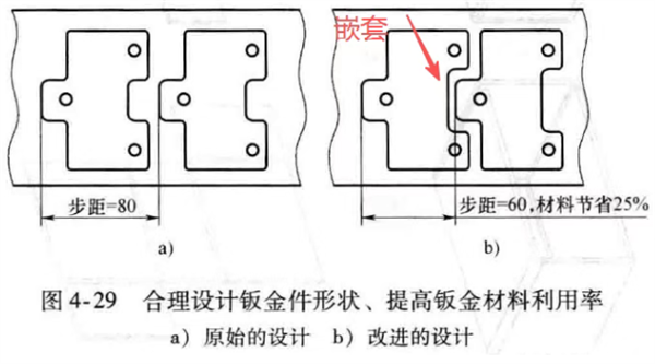
嵌套:nesting
步距 = 80:feeding pitch = 80
步距 = 60, 材料节省 25%:feeding pitch = 60, material saving rate reaches 25%
Figure 4-29 Optimize the shape of sheet metal parts to improve sheet metal material utilization
a) Original design
b) Improved design
Larger sheet metal parts require correspondingly larger stamping dies, which leads to higher die costs. Stamping dies are generally made of die steel or hard alloys (tungsten carbide, titanium carbide), materials that are difficult to machine and extremely costly. Dies become even more crucial when multiple stamping procedures are required for a single part.
Narrow and slender structures feature poor mechanical strength. Meanwhile, they cause severe material waste during layout and require a substantial increase in die dimensions.
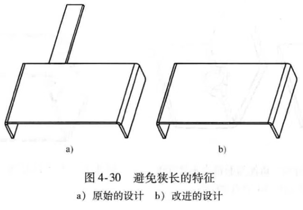
Figure 4-30 Avoid Narrow and Slender Features
a) Original design
b) Improved design
Parts that form a cross shape after unfolding result in heavy material waste and demand oversized dies. In the original design shown below, four bending edges are connected to a single base plate, forming a cross-shaped unfolded profile and causing massive material loss. The improved design restructures the layout: the central plate is only connected to two sub-panels, and subsequent plates are attached sequentially to the previous ones. This revision boosts material utilization by more than 30% and shrinks the overall outline of the stamping die.
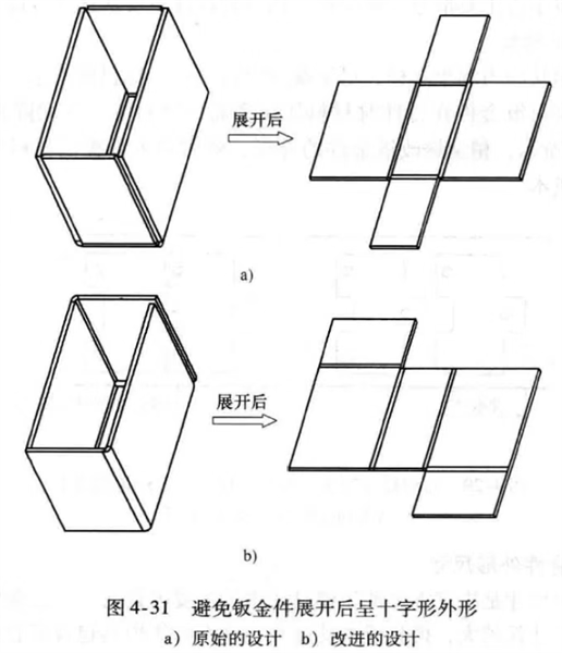
Figure 4-31 Avoid cross-shaped unfolded profiles of sheet metal parts
a) Original design
b) Improved design
Fabricating sheet metal parts with complex contours requires intricately designed punches and dies, which drives up die machining costs. Therefore, the outline of sheet metal parts should be kept as simple as possible.
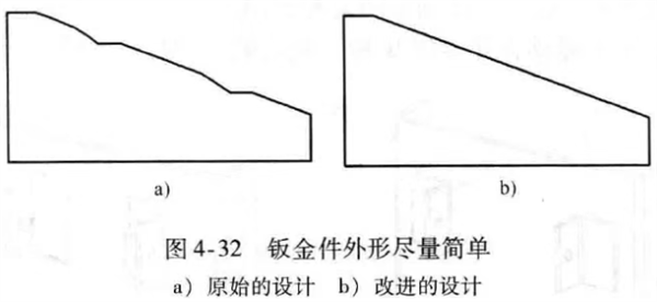
Figure 4-32 Keep the outline of sheet metal parts as simple as possible
a) Original design
b) Improved design
Stamping dies are categorized into two main types: single-operation dies and progressive dies. A complete set of single-operation dies consists of multiple process dies, including blanking dies, bending dies, forming dies and deburring dies. The more stamping procedures a part requires, the higher the production cost will be.
As illustrated in the figures: Design a features unreasonable bending flanges. After one bending operation, an additional forming process is needed for another attached feature. In Design b, however, both structural features share the same base. Two edges can be bent in just one stamping cycle.
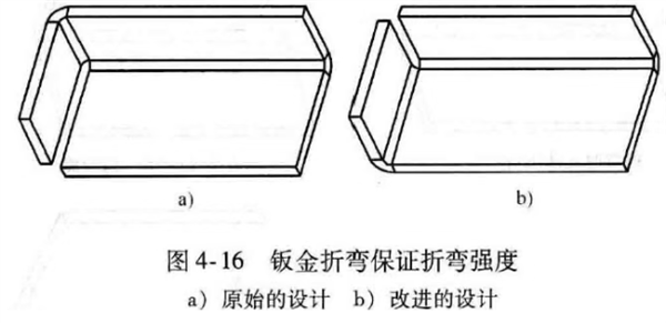
Figure 4-16 Ensure bending strength in sheet metal bending
a) Original design
b) Improved design
While reducing the total number of parts brings notable benefits, integrating numerous complex features into one component will lead to a geometric increase in process difficulty and production costs. Conduct thorough calculations to determine whether to split the part or retain the complex processing scheme.
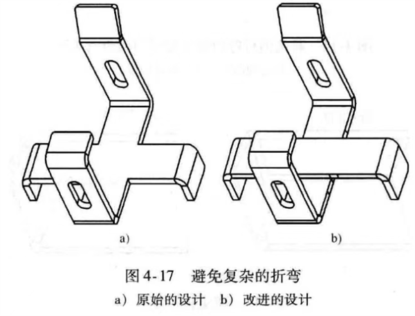
Figure 4-17 Avoid complex bending operations for sheet metal
a) Original design
b) Improved design
Reverse flattening requires two separate stamping strokes. Deburring is also an independent procedure. Where deburring is unnecessary, this process should be omitted to cut costs.
The costs of common sheet metal assembly methods are shown below:
Snap fit ≤ Blind rivet ≤ Self-clinching ≤ Spot welding ≤ Standard screw ≤ Manual screw
The original design in the figure includes three extra components, which require separate machining and additional assembly work. By fully utilizing blanking and bending processes, required structural features can be formed directly from the base sheet metal, eliminating extra parts.
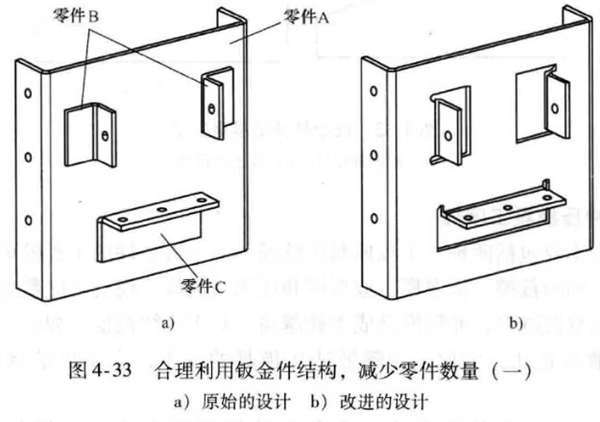
Figure 4-33 Reasonable use of sheet metal structure to reduce the number of parts (Part 1)
a) Original design
b) Improved design
During sheet metal design, prioritize standard holes and slots. This allows the use of off-the-shelf stamping dies and saves expenses on custom die development. In terms of material selection, choose commercially available sheet metals with standard thicknesses to lower material costs. You may search for standard stamping dies on commercial platforms; using ready-made standard dies can substantially reduce overall costs.
Main Design Guidelines for Sheet Metal Parts (Improving Sheet Metal Strength)


