Flat panels are the most common feature of sheet metal parts. Flat components made of relatively soft and thin materials generally have low strength and are prone to deformation under load. The strength of sheet metal parts can be improved by adding reinforcing ribs, performing bending, flanging and reverse flattening.
Reinforcing ribs are mainly available in two shapes: semicircular and trapezoidal. Their geometric dimensions shall be determined according to the thickness of the sheet metal, as shown in the figure below. It should be noted that excessive reinforcing ribs will instead cause component deformation, so they shall be evenly arranged on the sheet metal parts. Currently, most 3D design software can generate properly sized embossed features as reinforcing ribs based on sheet thickness.
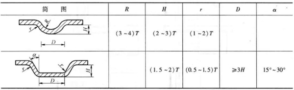
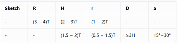
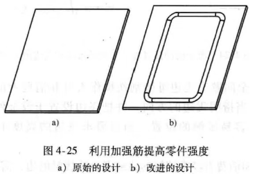
Figure 4-25 Improving Component Strength with Reinforcing Ribs
a) Original design b) Improved design
Increasing the section modulus can reduce bending stress.
When a bending moment M (N·mm) is applied to a workpiece, the resulting bending stress is calculated by the formula: σ = M / W
σ (Sigma): Maximum bending normal stress (bending strength), unit: MPa (Megapascal)
M: Maximum bending moment borne by the component section, unit: N·mm (Newton-millimeter)
W: Section modulus (bending section coefficient), unit: mm³ (Cubic millimeter)
For standard cross-sectional shapes in engineering, fixed formulas are applied to calculate the section modulus:
Rectangular section (width = b, height = h): W = b × h² / 6
Solid circular section (diameter = d): W = π × d³ / 32
I-beams and H-beams are widely used for structural reinforcement. H-beams deliver better overall performance than I-beams.
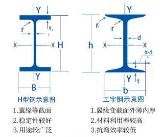
H-beam Features
I-beam Features
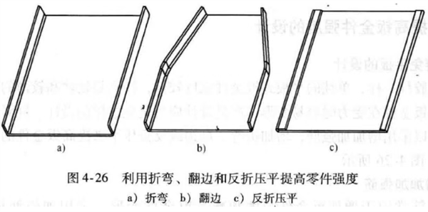
Figure 4-26 Improving Part Strength by Bending, Flanging and Reverse Flattening
a) Bending
b) Flanging
c) Reverse Flattening
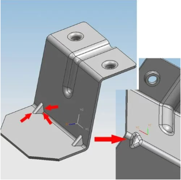
Triangular reinforcing ribs are installed at bending positions to further enhance local structural rigidity.
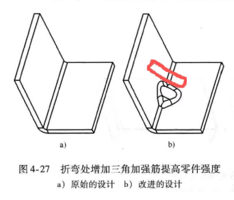
Figure 4-27 Adding triangular stiffeners at bending corners to improve part strength
a) Original design
b) Improved design
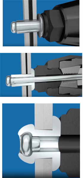
Integrating multiple bending edges into a unified structure can greatly improve the overall structural strength. As shown in the figures, three bending edges of the sheet metal are connected with blind rivets. Pre-drilled holes are required on the sheet metal, and a blind rivet gun is used to complete the riveting process.
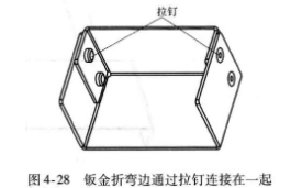
Figure 4-28 Sheet metal bending edges connected by blind rivets
拉钉:blind rivets
Main Design Guidelines for Sheet Metal Parts (Relief Notches and Burrs)


