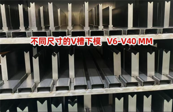
V-die grooves in different sizes: V6-V40 MM
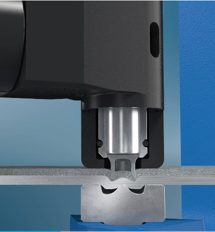
Bending is a key process in stamping. Its working principle is to apply external force to make metal materials produce plastic deformation, so as to form shapes with specific angles and curvatures. Common bending types include V-bending, Z-bending and reverse flattening.
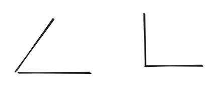
V-bending is the most basic bending method. A flat metal sheet is pressed into a V shape by dies. Its two bent sides meet at the bottom to form an acute angle or right angle.
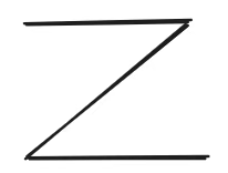
Z-bending is also known as Z-shape bending or double bending. Its final shape looks like the letter Z. This structure is widely used for offsetting planes, improving structural strength or serving as connection transitions.
Reverse flattening means first bending one side of the sheet into an acute angle (usually 90 degrees or less), then bending it in the reverse direction to make it fully fit against another part of the sheet.

Reverse flattening means first bending one side of the sheet into an acute angle (usually 90 degrees or less), then bending it in the reverse direction to make it fully fit against another part of the sheet.
The height of bent sheet metal shall be ≥2T+R. T stands for sheet metal thickness and R stands for bending radius. If the bending height is too low, deformation and distortion will easily occur, and the final dimensional accuracy cannot be guaranteed. This situation will appear in designs with inclined bending edges as shown in Figure 4-10. You can increase the height or cut off the parts with insufficient height.
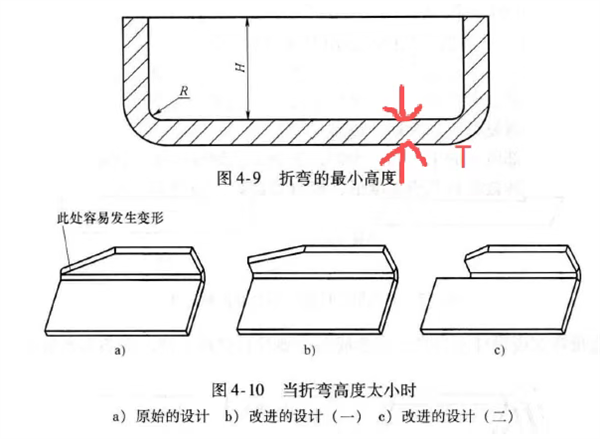
Figure 4-9 Minimum Bending Height
(annotations in diagram:
H: bending height
R: bending radius
T: sheet thickness)
Figure 4-10 Cases of Insufficient Bending Height
a) Original designb) Improved Design Scheme 1c) Improved Design Scheme 2(annotation: Deformation tends to occur at this position easily)
The actual bending radius of sheet metal shall be larger than the minimum bending radius. The minimum bending radius of different materials is shown in Table 4-2. T refers to sheet metal thickness. A larger bending radius is not always better. Excessively large radius will lead to more severe springback after bending.
To obtain a right angle, sheet metal manufacturers will adopt the scoring process. Scoring means pre-extruding a groove on the flat sheet to facilitate bending. However, parts made in this way are prone to fracture and have low structural strength.
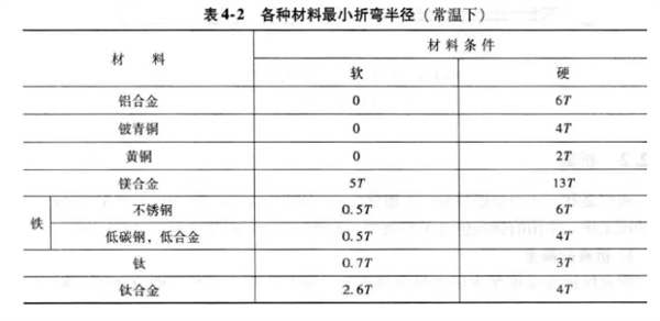
Table 4-2 Minimum Bending Radius of Various Materials (At Room Temperature)
Note: T = Sheet thickness
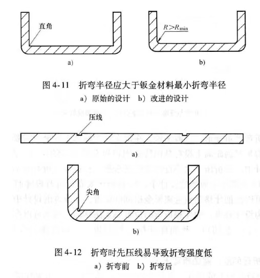
Figure 4-11
The bending radius must be greater than the minimum bending radius of the sheet metal material a) Original design (right-angle corner) b) Improved design (where R>Rmin)
Figure 4-12
Pre-scoring before bending easily results in low bending strength a) Before bending (showing score lines) b) After bending (showing sharp corners at the bend)
Avoid bending along the material grain direction, otherwise cracks will easily appear.
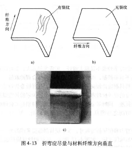
Figure 4-13 Bending should be as perpendicular as possible to the fiber direction of the material
a) Bending parallel to the fiber direction: cracks appearannotations: fiber direction, with cracks
b) Bending perpendicular to the fiber direction: no cracksannotations: fiber direction, no cracks
c) Actual part with bending cracks
Bending features cannot be placed too close to each other. The spacing shall be >2T+R.
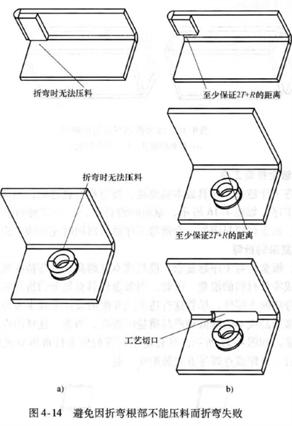
Figure 4-14 Avoid Bending Failure Due to Unclamped Material at the Bend Root
a) Original designs:
Cannot be clamped during bending
Cannot be clamped during bending (with a self-clinching fastener on the surface)
b) Improved designs:
Maintain a minimum distance of 2T + R
Maintain a minimum distance of 2T + R (with a self-clinching fastener on the surface)
Add a process notch (to allow clamping)
(Annotations in the diagram:
折弯时无法压料 = Cannot be clamped during bending
至少保证 2T+R 的距离 = Maintain a minimum distance of 2T + R
工艺切口 = Process notch)
A gap of at least 0.2mm must be reserved. Long and narrow bent sections have low strength, while short and wide bent sections feature higher strength.
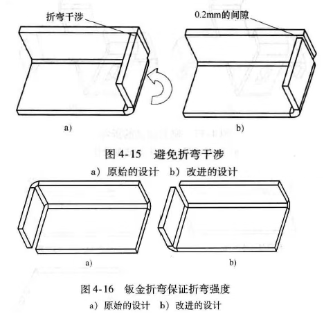
Figure 4-15 Avoid Bending Interferencea) Original design b) Improved design (with 0.2mm gap reserved to eliminate bending interference)
Figure 4-16 Guarantee Bending Strength for Sheet Metal Bendinga) Original design b) Improved design
As shown in Figure 4-16, the original sheet metal requires two bending processes. After optimization, two bends can be completed in one single process.
Although this solution will add one extra part, you still need to control the complexity of a single component. The two parts can be joined together by rivets, self-clinching fasteners or resistance spot welding.
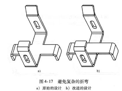
Figure 4-17 Avoid Complex Bending
a) Original design
b) Improved design
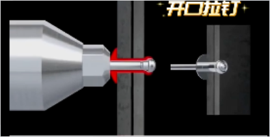
Open blind rivet