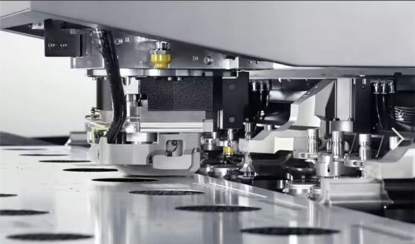
Blanking is a stamping process that uses a blanking die to separate sheet metal under the pressure of a press machine. It is a general term for various separation processes including punching, blanking, cutting, notching, and slitting. As a basic procedure in cold stamping, blanking can directly produce finished parts or prepare blanks for other cold stamping processes.
For rounded corners of sheet metal parts, the radius shall be no less than 0.5t and no less than 0.8mm.
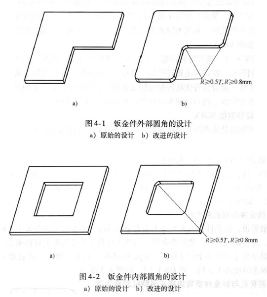
Fig.4-1 Outer corner design of sheet metal parts a) Original design b) Optimized design
Fig.4-2 Inner corner design of sheet metal parts a) Original design b) Optimized design
First, safety consideration. Sharp outer corners of sheet metal parts are extremely sharp, which may easily cut operators’ fingers during manufacturing and assembly. They may also injure users or maintenance personnel during product use and repair.
Second, stamping die consideration. Sharp corners on sheet metal correspond to sharp corners on the mold. Sharp corners on the die cavity are difficult to machine and prone to cracking during heat treatment. Meanwhile, sharp corners on the punch are likely to suffer edge chipping and excessive wear during blanking, greatly shortening mold service life.
The width of slots or cantilevers shall satisfy A ≥ 1.5T.
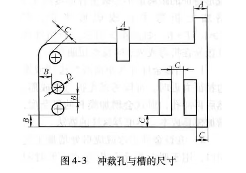
Fig. 4-3 The dimensions of the punching holes and grooves
Avoid designing overly long cantilevers and narrow slots on sheet metal parts. Otherwise, the corresponding punch on the stamping die will be small in size and low in strength, resulting in short mold service life.
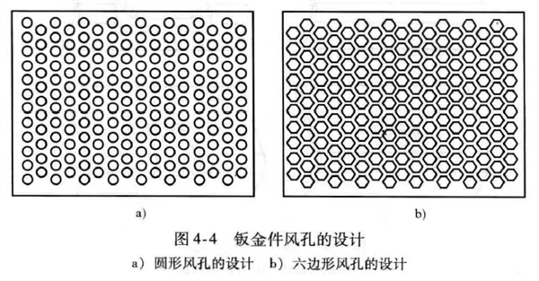
Figure 4-4 Design of Vent Holes in Sheet Metal Parts
a) Design of Circular Vent Holes b) Design of Hexagonal Vent Holes
Round holes are the preferred option for sheet metal punching, as they are easier for mold machining. Common ventilation hole types include round holes, hexagonal holes and square holes.
Round holes feature a lower opening ratio and poor heat dissipation. Hexagonal ventilation holes offer a higher opening ratio and better heat dissipation, but the mold processing is more complicated. Square ventilation holes have the highest opening ratio, yet their right-angle corners cause severe mold wear.
Therefore, when designing ventilation holes, comprehensively balance mold machinability and heat dissipation performance. Under the premise of meeting heat dissipation requirements, round holes shall be prioritized.
Refer to Figure 4-3.
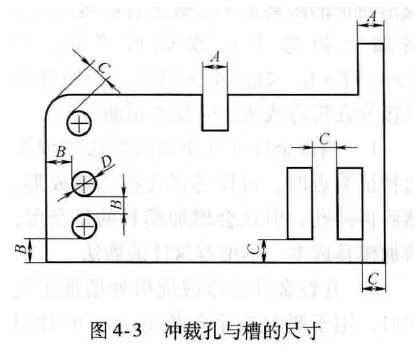
The dimensions of the punching holes and grooves
Generally, the minimum punching diameter of sheet metal shall be 1.5 times the sheet thickness. Undersized holes result in small punch dimensions, which are easy to break or bend and have a short service life.
The minimum punching size is also related to material properties. For soft materials, the minimum punching size can be smaller than the sheet thickness; for hard materials such as stainless steel, the minimum punching diameter shall not be less than 1.5 times the sheet thickness, namely D ≥ 1.5T. Refer to Figure 4-3.
Punching is normally conducted before bending.
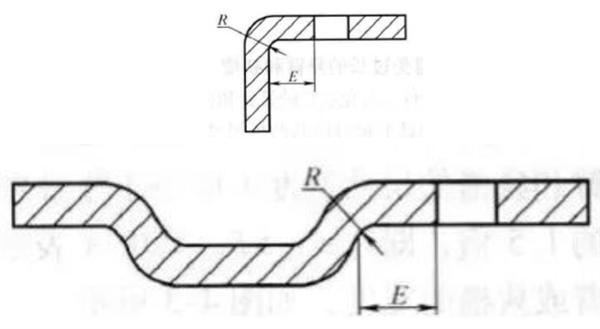
The minimum distance between blanking holes and sheet metal bend edges or formed features shall be 1.5 times the sheet thickness plus the bend radius or forming radius, namely E ≥ 1.5T+R. Refer to Figure 4-5.
Otherwise, blanking holes are prone to distortion during bending and forming.
Add process notches at bending or forming positions to absorb deformation, so as to ensure the quality of punched holes. Refer to Figure 4-6.
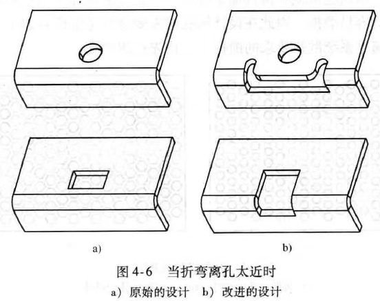
Figure 4-6 When the bending distance from the hole is too close
a) The original design b) The improved design
Engineers usually design sheet metal in 3D models and tend to ignore the verification of blanking clearance after flat unfolding. It is common to encounter overly small blanking clearance or even material interference after unfolding. The more complex the sheet metal structure, the higher the probability of such errors.
Take process notches shown in Figure 4-7 as an example. Unreasonable notch size leads to insufficient blanking clearance after unfolding, which reduces punch strength and shortens mold life.
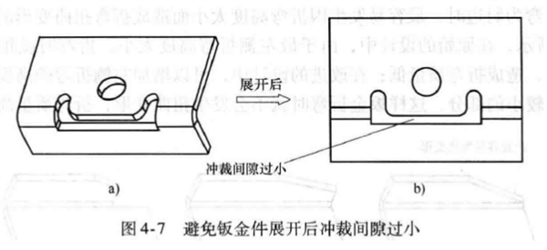
Figure 4-7 Preventing the punching gap from being too small after the sheet metal part is unfolded
Unreasonable design of sheet metal bend width will also cause material interference after unfolding, which can be checked by viewing the unfolded layout of sheet metal parts. Refer to Figure 4-8.
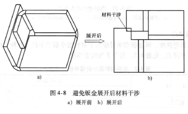
Material interference
Figure 4-8 Avoiding material interference after sheet metal unfolding
a) Before unfolding b) After unfolding


