In industrial additive manufacturing, the transition from a digital CAD model to a physical part is governed by the laws of thermodynamics and laser optics. The two most persistent challenges for engineers are the loss of fine structural details and dimensional warping in large-scale builds. This technical report outlines the root causes of these phenomena and the specific mitigation protocols used at Justway’s production facility.
1. Micro-Feature Loss: Navigating Physical Limits
When delicate pins, thin walls, or micro-textures "disappear" or fail during the build, it is typically a result of reaching the physical boundaries of the process.
Root Cause Analysis:
- Laser Spot Constraints: Our industrial SLA systems utilize laser spots between 0.06mm and 0.12mm. Any feature designed below this threshold risks being "skipped" by the slicing algorithm.
- Green Strength Deficit: During the liquid-to-solid transition (SLA) or sintering (SLS), thin features lack the structural "green strength" to withstand the mechanical force of the recoater blade or resin surface tension.
- Post-Processing Stress: Features thinner than 0.3mm often lack the mechanical resilience to survive high-pressure air cleaning or manual support removal.
Justway’s Technical Standards:
- Minimum Wall Thickness: We recommend a minimum functional wall thickness of 0.8mm. For non-load-bearing aesthetic details, the absolute limit is 0.5mm.
- Base Reinforcement: To preserve vertical pins or thin ribs, we suggest adding 0.2mm - 0.5mm fillets at the base to dissipate stress concentration.
- Specialized Slicing: For high-detail requirements, we activate "Thin-Wall Compensation" algorithms to force laser paths into sub-millimeter geometries.
2. Warping & Deformation: Managing Thermal Stress
Warping is the result of accumulated internal stresses as layers cool and contract. It is the primary cause of dimensional failure in large or long geometries.
Critical Risk Scenarios:
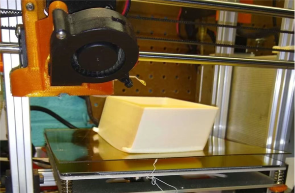
- Large Horizontal Surfaces: Printing flat plates parallel to the build platform creates massive shrinkage force at the edges.
- High Aspect Ratios: Parts exceeding 200mm in length accumulate significant linear contraction, leading to "curling" at the extremities.
- Uneven Mass Distribution: Sharp transitions between thick and thin sections cause non-uniform cooling rates, triggering internal twisting.
Justway’s Anti-Warping Protocols:
- Optimized Orientation Strategy: We avoid horizontal placements. By tilting parts at 15° to 30°, we reduce the surface area of each individual layer, allowing contraction stress to dissipate gradually.
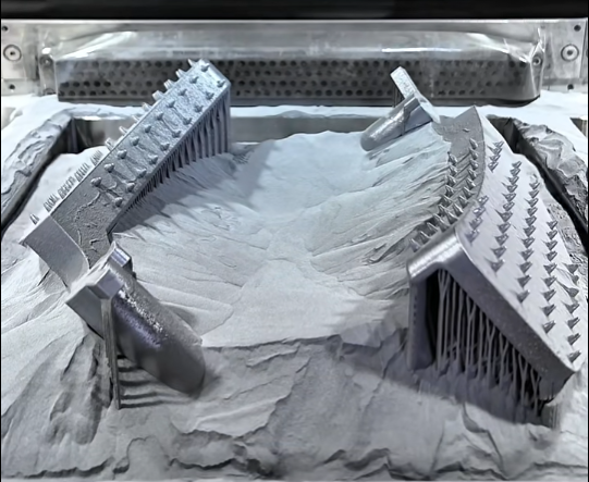
- High-Tensile Support Anchoring: For large builds, we utilize "Heavy-Duty" support arrays. These act as mechanical anchors that physically lock the part’s perimeter to the build plate, resisting the upward pull of shrinkage.
- In-Chamber Thermal Stabilization: For SLS Nylon, we maintain the build environment within ±1°C of the material’s crystallization temperature to prevent the rapid thermal delta that triggers warping.
3. Technical Summary & Design Benchmarks
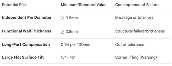
Potential Risk Minimum/Standard Value Consequence of Failure
Independent Pin Diameter ≥0.5mm Breakage or total loss
Functional Wall Thickness ≥0.8mm Structural failure/brittleness
Long-Part Compensation 0.1% per 100mm Out of tolerance
Large Flat Surface Tilt 15° - 45° Corner lifting (Warping)
Return to Index:
Justway Technical Resource Center


