A Professional Guide for Structural Engineers
(Core concepts adapted from Bilibili creator: Z-Engineering Structural Design Workshop)
For anyone new to structural design, snap-fit joints are one of the first features you’ll encounter. Because they rely entirely on elastic deformation, beginners often struggle with tolerances and dimensions. This article breaks down ten critical design considerations.
----------------------------------------------------------------------------------------------------
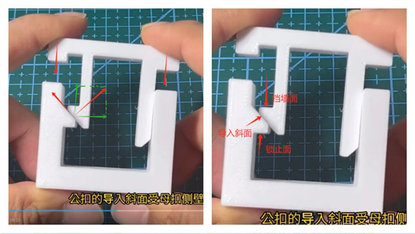
Too shallow, and the snap requires excessive rotation to engage, driving assembly force through the roof. Too steep, and it loses its "lead-in" function. 30°–45° is the sweet spot where axial assembly force converts to radial opening force most efficiently.
If the male snap tip and female entry feature sharp corners, assembly will shave the plastic surface, causing Stress Whitening—microscopic crazing from material fracture. A fillet radius aids mold filling and eliminates gas trapping.
--------------------------------------------------------------------------------------------------------
A snap arm is fundamentally a cantilever beam. If its thicness equals or exceeds the base wall, sink marks form during injection molding. Worse, excessive rigidity prevents elastic deformation during assembly.
Target deflection: 5%–8% of the beam length—this aligns with the elastic limit of common engineering plastics (ABS, PC, PA). Exceed this, and the snap undergoes permanent plastic deformation, loosing retention force.
---------------------------------------------------------------------------------------------------------------------
90° Vertical Face: The retention surface is perpendicular to the pull-out direction; disengagement force is resisted purely by the material’s shear strength.
2°–5° Reverse Undercut: Dramatically increases retention force. However, standard injection molding cannot release this geometry without forced ejection (stripper) or side-action slides—mold cost spikes significantly.
-------------------------------------------------------------------------------------------------------------
During repeated assembly/disassembly, the inner corner at the beam root suffers extreme stress concentration (Kt).
A radius of R ≥ 0.5 mm is mandatory; aim for R ≥ 1.0 mm where space allows. This lets stress flowlines transition smoothly, drastically improving fatigue life.
------------------------------------------------------------------------------------------------------------
Balance snap forces to prevent shell warping or squeak/rattle from uneven loading. Differentiating geometry (asymetric features) prevents reverse assembly.
---------------------------------------------------------------------------------------------------
Snap undercuts handle tensile stress—plastics excel here. Stop lands, BOSS ribs, and locating pins handle shear stress.
During drop testing, impact force typically travels along the diagonal (X/Y shearing direction). Snap arms are extremely vulnerable to horizontal shearing; loaded this way, they shatter instantly (Shock Break) and fail the test.
-------------------------------------------------------------------------------------------------------
Plastics creep. Six months after assembly, polymer chains rearrange, causing the snap to relax and create micro-gaps. Once a gap exists, vibration generates squeak & rattle.
Crush Rib (raised micro-rib): Flattens during assembly (0.1–0.2 mm plastic deformation). The material’s elastic recovery provides continuous normal force, clamping the halves together, eliminating all stack-up tolerance, and absorbing high-frequency vibration.
-----------------------------------------------------------------------------------------------------------------
Lifter: The most common side-action mechanism in injection molds, but it consumes cavity base space, increases mold stack height, and raises ejection risk.
Through-Hole: A clearance hole beneath the cantilever arm. The arm deflects into open air—no complex slides or lifters needed. Simply insert a pin. Mold cost drops 20–30%, and binding is eliminated.
-----------------------------------------------------------------------------------------------------------------
Any joint labeled "serviceable" must include a flat screwdriver or spudger entry point and fulcrum along the shell edge.
Too many beginners draw the snap but forget the tool access. Service becomes a destructive snap-break. Slot depth must exceed tool thicness (>1 mm) and must avoid PCB traces and fragile components.
-----------------------------------------------------------------------------------------------------------------------
During assembly, as the male lead-in angle presses the female feature, the snap arm does not translate purely downward—it traces an arc (rotation path) about its root.
In your CA model, run a motion study or manually sketch the enveloe. Verify that this swept arc clears PCB boards, gold fingers, FPC cables, and capacitors.
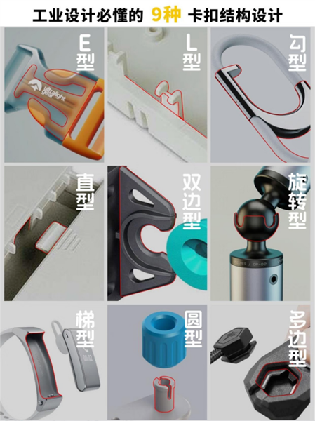
1.E型E-Type Snap / E-Profile Cantilever Snap
2.L型L-Type Snap / L-Profile Snap-Fit
3.勾型Hook-Type Snap / J-Hook Snap-Fit
4.直型Straight-Type Snap / I-Beam Cantilever Snap
5.双边型Double-Sided Snap / Two-Way Snap-Fit
6.旋转型Rotary Snap / Swivel Lock Joint
7.梯型Ladder-Type Snap / Trapzoidal Snap-Fit
8.圆型Circular Snap / Cylindrical Retention Ring
9.多边型Polygon Snap / Polygonal Torque Lock
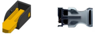
The E-type snap fit combines a robust, professional appearance with a sophisticated internal structure. Reinforcing ribs on both sides of the snap significantly enhance its load-bearing capacity. The contact surfaces feature anti-slip texturing to prevent accidental disengagement during use.
Renowned for its clean, lightweight design, the L-type snap fit is optimized for rapid assembly and disassembly—ideal for applications requiring frequent component replacement. All edges and corners are radiused, delivering both refined aesthetics and protection against scratch hazards during handling.
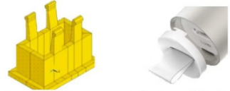
The hook-shaped geometry securely engages and retains the mating component for a stable connection. The hook section is manufactured from a specialized material that delivers both sufficient strength and controlled elasticity, preventing permanent deformation under load.
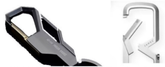
Featuring a simple, direct design with clean, fluid lines, the straight-type snap fit employs a precision-machined connection interface to ensure a tight, gap-free fit. It also offers excellent corrosion resistance, maintaining stable performance even in humid environments.
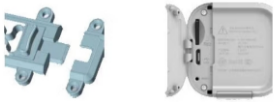
The defining characteristic of the double-sided snap fit is its dual retention force. Anti-slip grooves are engineered on both sides to effectively prevent component sliding under load. The material is rigorously selected to ensure adequate strength and long-term durability.
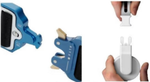
Engineered for intuitive operation, the rotary snap fit engages or releases through a simple rotation. The rotating mechanism incorporates precision gear geometry to ensure smooth, stable actuation.
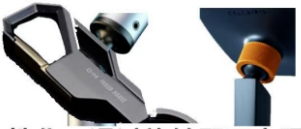
(Note: The body text in the image duplicates the straight-type description.)
Featuring a simple, direct design with clean, fluid lines, the ladder-type snap fit employs a precision-machined connection interface to ensure a tight, gap-free fit. It also offers excellent corrosion resistance, maintaining stable performance even in humid environments.
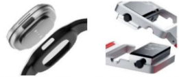
Widely favored for its rounded aesthetics and comfortable tactile feel, the circular snap fit uses radiused corner geometry that is not only visually appealing but also eliminates sharp-edge injuries during use.
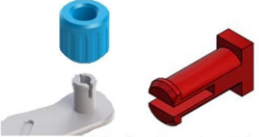
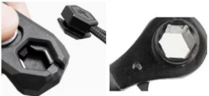
The polygon snap fit offers a flexible, adaptable design that can be customized to meet diverse connection requirements. Each edge is meticulously finished to ensure smooth engagement and connection stability.