Last month, an industrial product founder reached out to me. His product featured a fully integrated CNC-machined aluminum enclosure. Visually stunning, cool solid-metal feel when you set it on a desk — almost like a work of art.
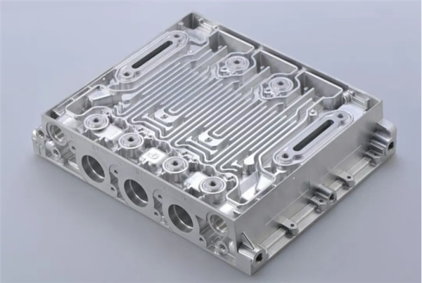
Then he showed me the quotation: $385 per single housing.
He asked, “Why is it so expensive?”
I told him: “Your design ignores machining manufacturability. Every cutting pass burns cash.”
With 15 years of electronic structural design experience, I have encountered countless pitfalls with metal enclosures. Today I want to talk about something many designers overlook: spend 10 minutes on DFM checks at the design phase, and you can cut mass-production costs by 30%.
Many designers draw sharp 90° internal corners.
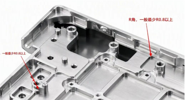
CNC end mills are cylindrical tools and cannot machine perfectly sharp inside corners. If you specify sharp corners, the shop must switch to smaller tools for corner clearing. These small cutters break easily, doubling machining cycle time and crashing yield rates.
Best practice: Add radii to all internal corners. Minimum R0.5 mm; R0.8 mm or larger is recommended. This single fix can reduce unnecessary machining time by 20%.
Metal enclosures often include undercuts and grooves, typically machined with T-slot cutters.
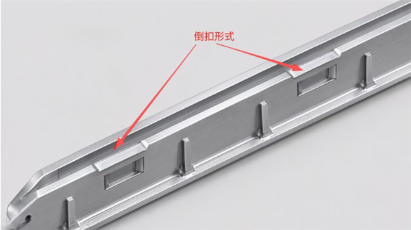
Some designers specify T-slot width as 0.8 mm. It may look sleek on CAD, but this causes constant tool breakage and huge frustration for machinists.
T-slot width should be 1.5 mm minimum, with end radii of at least R2. The narrower the slot, the slower the machining and higher the cost. That tiny clearance gain you wanted will land you an eye-watering machining quote.
For aluminum housings, the absolute minimum wall thickness can reach 0.8 mm, and magnesium alloy can go as thin as 0.45 mm.
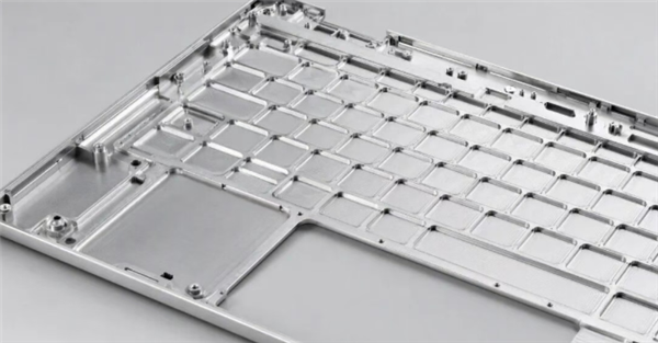
But once you hit 0.8 mm, any post-processing — anodizing, bead blasting, polishing — will warp or bend thin walls. Parts may also deform from residual mechanical stress during machining.
Design recommendation: Aluminum ≥1.2 mm; magnesium alloy ≥0.8 mm. Do not sacrifice mass-production yield for ultra-thin aesthetics.
Designers often default to ±0.02 mm tolerances, believing tighter precision is always better.
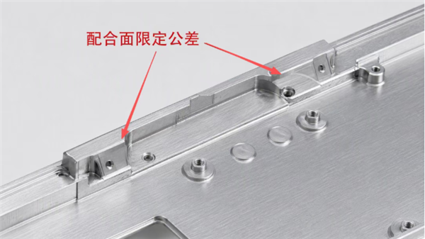
CNC machining is not 3D printing. Every upgrade in tolerance grade can multiply machining costs by 2–3 times.
Non-mating surfaces only require ±0.1 mm. Reserve ±0.05 mm for mating interfaces only. Relax tolerances for non-critical features; use screw adjustment wherever possible instead of chasing ultra-precise CNC dimensions.
Snap-fit mating features are common on enclosures. Few engineers realize: female recessed snap features are far faster to machine than male protruding snaps.
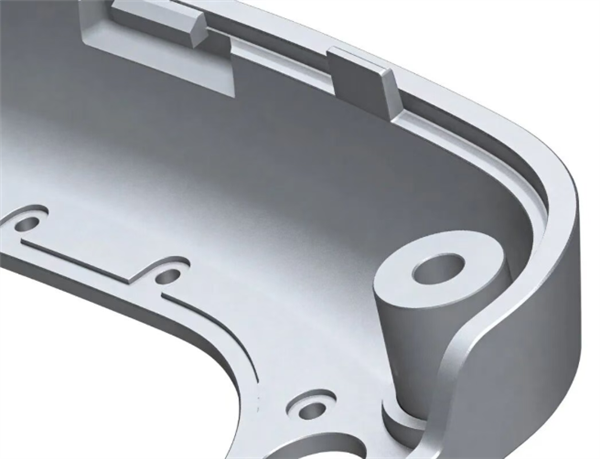
Male snap features require multiple tool changes and complex toolpaths; their machining cycle time is 2–3x longer than female counterparts.
Use female snap geometry wherever you can. Same visual performance, yet cost is cut nearly in half.
When reviewing your metal enclosure design, ask these DFM questions:
Are all internal corner radii ≥ R0.5? If not, expect at least a 20% machining cost premium.
Is every T-slot wider than 1.5 mm? Redesign if not.
Are wall thicknesses uniform? Uneven thickness guarantees warping after post-processing.
Are tolerances unnecessarily tight? Loosen non-critical dimensions to save up to 30% on machining.
Is your snap-fit geometry optimized? Prefer female recessed snaps whenever feasible.
These checks take just 10 minutes during design review, yet they can save tens of thousands to hundreds of thousands in production machining expenses.


